Bow thruster propeller damage – vibration detection
Abstract: Article describes case study of damaged bow thruster. Shows how to connect peaks from FFT velocity spectrum to link with characteristic parts of devices.
1. Introduction
Bow thruster is a very important machine for each vessel. Without working bow thruster, berthing in port is more costly or can even be impossible due to safety rules. Taking above into consideration, the technical condition of bow thruster is very important and should be maintained on good level. The most effective way to maintain good condition of machinery is condition-based maintenance (CBM). Implementation of CBM gives information about actual condition of machine based on measurements. The three main methods which are used in that kind of maintenance are: vibration measurements, oils analysis and temperature measurements. Condition monitoring of thruster usually is based on two methods:
• Oil analysis of hydraulic and lubrication system
• Vibration measurements
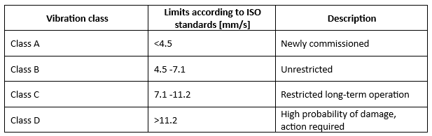
Bow thrusters and their gear parts are classified in the ISO 20283-4 standard. Table 1 presents limits and description for each class. According to that standards vibration below 7.1mm⁄s RMS (root mean square) are unrestricted and not any maintenance is needed. Vibration over 7.1mm⁄s but below 11.2mm⁄s are classified as class C, it means that device is restricted for long-term operation. Class D is for Vibration over 11.2mm⁄s and device which vibrate so much is probably damaged, and action is required.
Table 1 Legend according to vibration class
2. Case study
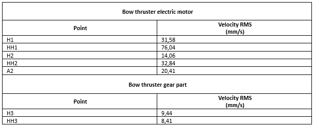
Picture 1 shows precise location of measurement point on bow thruster. As shown there are 5 measurements points on bow thruster el. motor: two radial points on NDE (non-drive end), two radial points and one axial on DE (drive end). There are also 2 radial points on gear part of bot thruster.
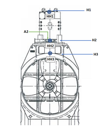
Picture 1 Location of measurement points
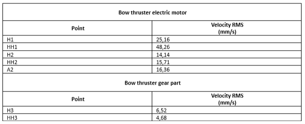
During standard analysis high vibration on bow thruster el. motor have been detected. As shown in table 2, the highest overall amplitude of the signal was 76mm/s (velocity RMS) – it was observed on one of NDE points with 80% of thruster’s load. Vibration on other el. motor’s points was also classified as class D.
Table 2 Overall values of vibration with 80% load of thruster’s
Picture 2 presents FFT velocity spectrum from the most vibrating point, so from HH1. As it is observed there are there are three peaks higher than others. Frequency associated with the highest peak is 21Hz, which is corresponding to revolution speed of electric motor. Second highest peak is associated with 16,5Hz and the last but not least is 5,5Hz.
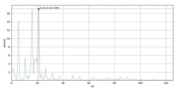
Picture 2 FFT velocity spectrum from point HH1
According to technical information about the bow thruster, it is known that gear ratio is 1:3,81 and that propeller has 4 blades. This information was used to determine that peak on 5,5Hz is corelated to shaft propeller speed, calculation are shown below.
21 ÷ 3,81 ≈ 5,5 [Hz]
The last peak, that one on 16,5Hz is not peak corelated with normal operation of this thruster, but it was noticed that 16,5Hz is exactly 3 times the propeller shaft frequency. Moreover the blade pass frequency, which would be 4 timed propeller frequency, was not noticed. Conclusion of that analysis is that, probably, one of the blades is damaged or missing.
The diver’s photos, picture 3, confirmed our assumptions.
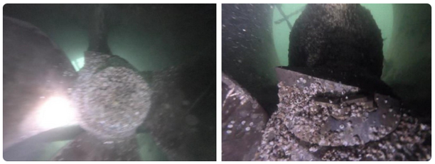
Picture 3 Diver’s photos
After this discovery, it was important to the owner of the vessel to extend working condition of bow thruster till dry dock. Due to that additional measurements were taken to estimate what load is appropriate for maneuvering with bow thruster.
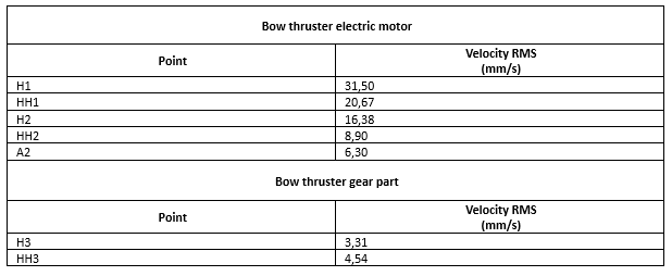
Tabel 3 presents results from bow thruster with 50% load. Vibration are significantly lower than these presented in table 2, but still all electric motor’s points are classified as class D, which is obvious because the impeller is damaged. The strongest vibration are observed on non-drive end as previous.
Table 3 Overall values of vibration with 50% load of thruster’s
Tabel 4 presents measurements results from bow thruster working with 0% load. With these measurement condition overall values still are high and some points still are classified as class D. Similar to previous measurements non-drive end is the strongest vibration are observed on non-drive end.
Table 4 Overall values of vibration with 0% load of thruster’s
Based on taken measurements, it was decided that bow thruster should be working up to 50% of load and measurements interval should be shortened to maximum 2 weeks.
The essential information for the owner before dry dock was if the other parts, expect propeller, were damaged. Luckily, diagnosis confirmed that gearbox was in good condition.
References:
[1] ISO Standard 20283-4:2012 “Mechanical vibration — Measurement of vibration on ships — Part 4: Measurement and evaluation of vibration of the ship propulsion machinery”
[2] James E. Berry P.E. Technical Associates Of Charlotte, P.C. “Analysis I How to implement an effective condition monitoring program using vibration analysis” Second Edition 06.1997
[3] M.Luft, PRUFTECHNIK AG “Machinery diagnosis: Quick and easy through FFT analysis” 05.2010